How to use Immersity AI Features
Overview
Immersity AI empowers you to effortlessly infuse life into your 3D photos through animation effects. It's as easy as dragging and dropping a photo onto the Immersity AI web site and immediately seeing the result. In many cases that is all you will need to do. Default settings have been tuned to allow many use cases to work just out of the box. Nevertheless, we encourage you to use the more advanced features of the app to get the most out of your animations.
Beyond Animations, Immersity AI enables versatile utilization of the 3D data that it generates for other purposes. it's not just about the animations - you can take the 3D information generated by Immersity AI and uses it in 3rd party applications. This tutorial will focus on the app itself and dive into some of the advanced features of the animation produced by it. However, be aware that we also cover the use of Immersity AI exported data for other purposes in additional tutorials listed here for your convenience:
Getting Started
It all starts with an import of an image into Immersity AI.
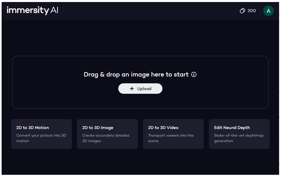
Follow these simple steps:
1. Log in on Immersity AI
2. Upload an image from your device either by drag & drop or by pressing the upload button
3. Wait for image processing. Once complete a 3D animation will appear
This also opens up a menu as follows that we will now cover in more detail in the sections to follow:
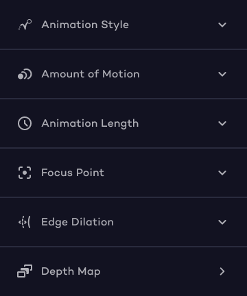
Animation Settings
There are a number of settings you can use to control the animation of your image from the main menu. These are explained in more detail in the table below.
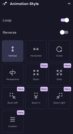
Several fundamental paths are available for your benefit. As you traverse more axes, a greater amount of parallax data is conveyed, enhancing the perception of depth. Therefore, in the sequence of heightened depth perception, the settings are outlined as follows:
- Single-axis movement: Horizontal, Vertical, Zoom, Dolly (x, y or z direction only)
- Dual-axis movement: Circle (both x and y directions)
- Triple-axis movement: Perspective, Zoom left, Zoom in, Zoom right. This involves traversing a path that uses all axis (x, y, and z directions).
Loop: when this switch is set the animation loops to avoid jumps
Reverse: this switch reverses the animation so that it plays backwards


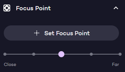
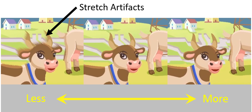
- Far: the background remains fixed whilst the foreground moves.
- Between Far and Close: Foreground and Background move in opposite directions. The amount of motion in each depends on slider position.
- Close: the foreground remains fixed whilst the background moves.

Animation Styles
There are a number of different animation styles available to you. Note that style suitability is quite image dependent and not all styles are necessarily suitable in all cases. To guide you in determining the right style for your specific use case and achieving the best possible effect for your image, we will delve into each style in greater detail in this section.

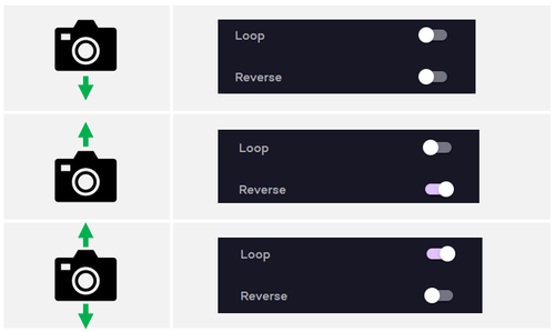
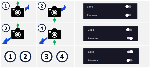
- If reverse switch is off then if moves down only
- If reverse switch is on then it moves up only
- If loop switch is on then it moves up and down


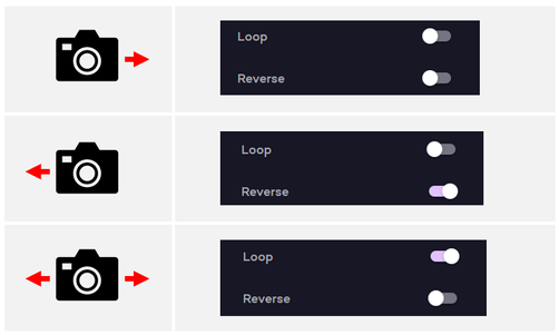
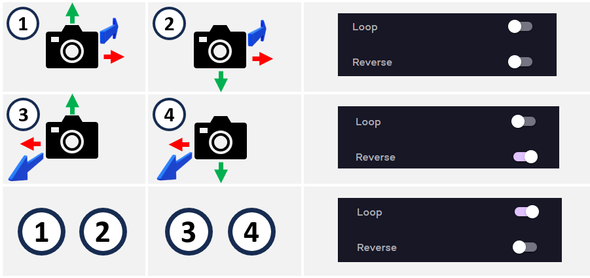
- If reverse switch is off then it moves right only
- If reverse switch is on then it moves left only
- If loop switch is on then it moves left and right


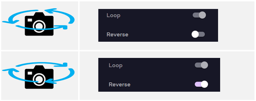
- the Loop switch is permanently on since circular motion loops naturally.
- If reverse switch is off then it moves counter-clockwise
- If reverse switch is on then it moves clockwise


- the Loop switch is permanently on since circular motion loops naturally.
- If reverse switch is off then it moves counter-clockwise (as viewed from top)
- If reverse switch is on then it moves clockwise (as viewed from top)


- If reverse switch is off then it moves forwards into the screen (zoom in)
- If reverse switch is on then it moves back out of the screen (zoom out)
- If loop switch is on then it moves back and forwards.
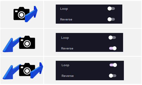


- If reverse switch is off then it moves forwards into the screen (zoom in)
- If reverse switch is on then it moves back out of the screen (zoom out)
- If loop switch is on then it moves back and forwards.

This type of zoom was popularized by director Alfred Hitchcock in the 1958 film "Vertigo." and results in a deliberate visually unsettling effect.






To do this, press one of the pre-configured styles first to obtain default settings for that style and then select the Custom style. Then open up Manual Settings to access controls that allow you to further refine and customize away from these defaults. A shortcut to this is to simply dive into the Manual Settings even when you still have a pre-configured style set. The Custom style will automatically select itself once you start editing.
Furthermore, you don’t have to select a pre-configured style first. If you don’t want to base your customization on any particular pre-configures style you can go ahead and dive straight into the Custom style and charge ahead making changes to create your own effect.
Please be aware that in Manual Settings we permit a broad spectrum of values to be configured intentionally. This flexibility is provided to facilitate the creation of special effects without imposing excessive constraints on you. However, it's important to note that while extreme values may enhance the visual appeal of certain images, they might not be suitable for many others. We have established reasonable default values, but feel free to explore and go beyond these defaults by entering Manual Settings yourself if desired.
More detail on Manual settings can be found in the Manual Settings section of this document.
Example:

Manual Settings
Manual settings allows you to have more control of the animation motion path beyond the pre-set options provided with Animation Style settings alone. Observe that as you change the Animation Style the settings in the Manual settings change automatically, so you can directly see what these presets are in terms of Manual settings. So from a workflow perspective, you can:


Manual Settings - Circular Mode
To understand what is happening in this mode, we need to understand some basics first. The animations are generated by oscillating the observer point of view along a path. This path is a 3 dimensional path as it takes place in 3 dimensional space and hence uses 3 oscillators to control the motion. Think of these oscillators as tugging the viewer into a particular direction in a wave type back and forwards motion. Each oscillator is responsible for one axis of motion as follows:
- x-axis: this is for motion in left/right direction
- y-axis: this is for motion in up/down direction
- z-axis: this is for motion in depth direction (into and out of image)
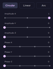
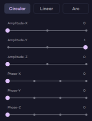
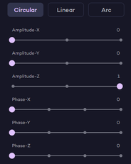
These 3 oscillators can be applied individually or in combination to work together to produce the animation. The amount each is applied is controlled by the Amplitude X, Amplitude Y and Amplitude Z sliders respectively. For example, to just cause left/right motion, you would set Amplitude X to some value and set Amplitude Y and Amplitude Z to zero effectively turning oscillators for y-axis and z-axis off altogether. However you can have all 3 of them working at the same time in which case you would have non-zero values for each to varying degrees.
Using One Axis
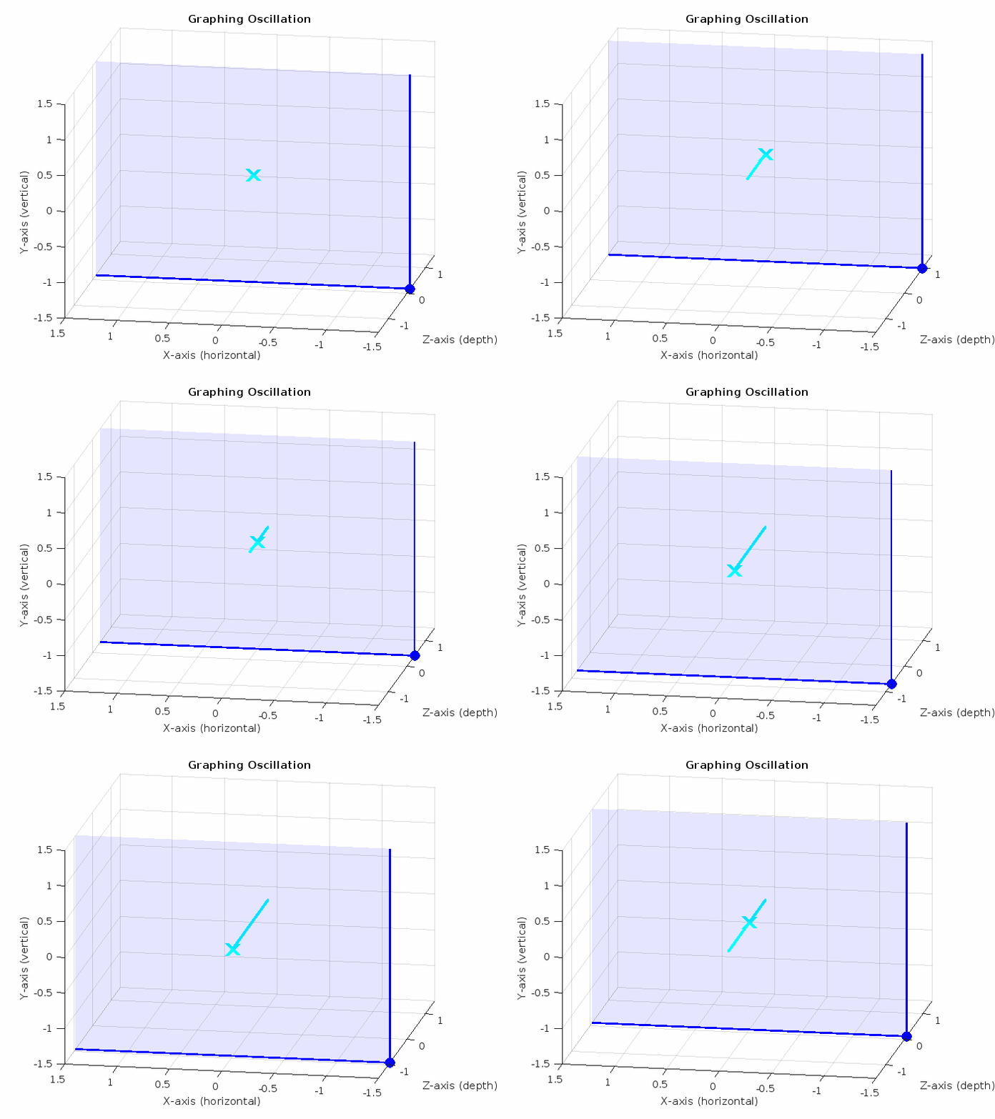
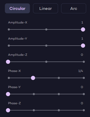
By only setting one of the Amplitudes to a value and leaving the others at zero, the viewer will only be tugged back and forwards in that direction. Phase is irrelevant for one axis, so this can be set to any value and for simplicity we set it to zero here. We will explain phase in the next section where it becomes relevant. This produces a linear straight line motion as follows:
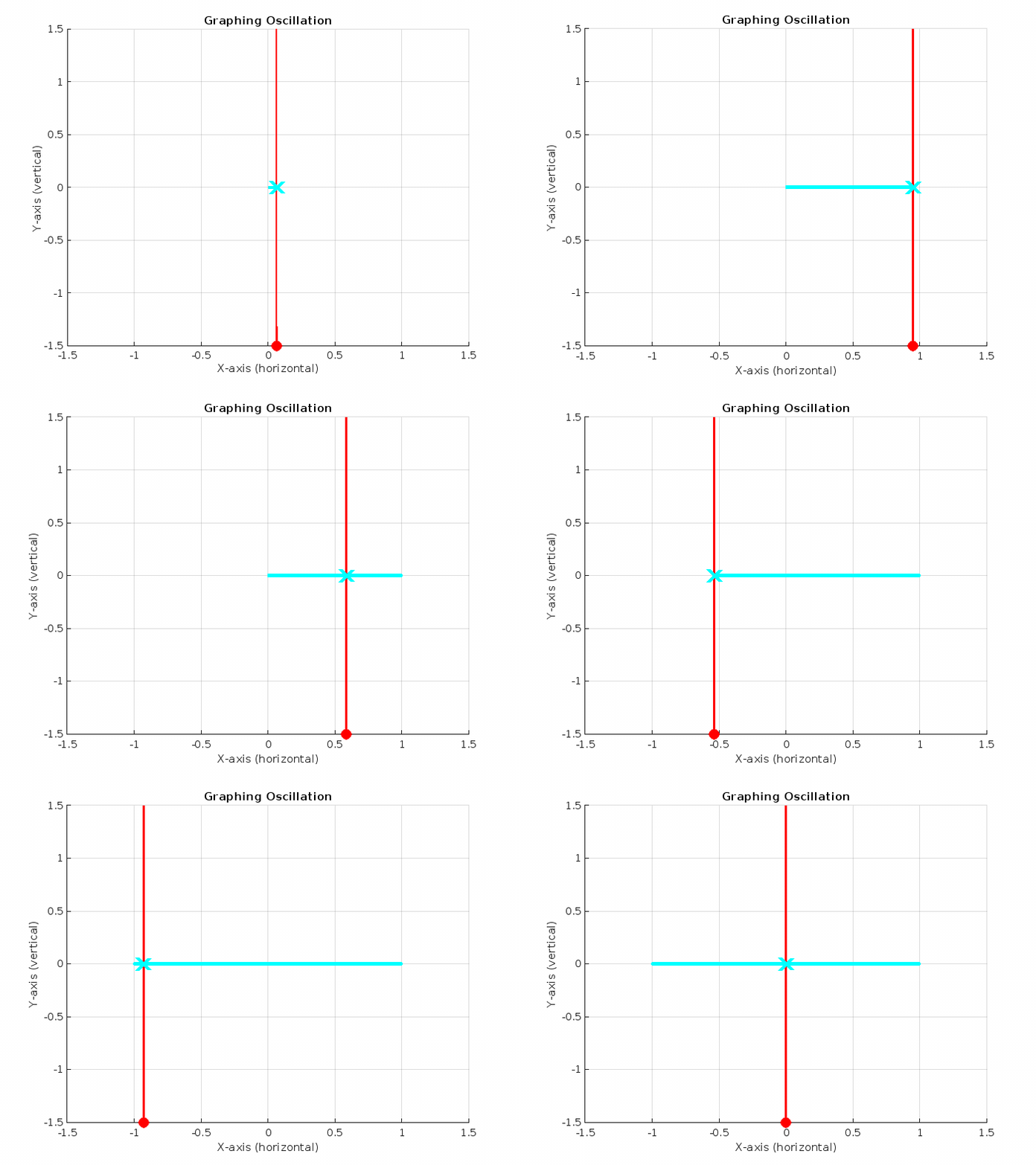

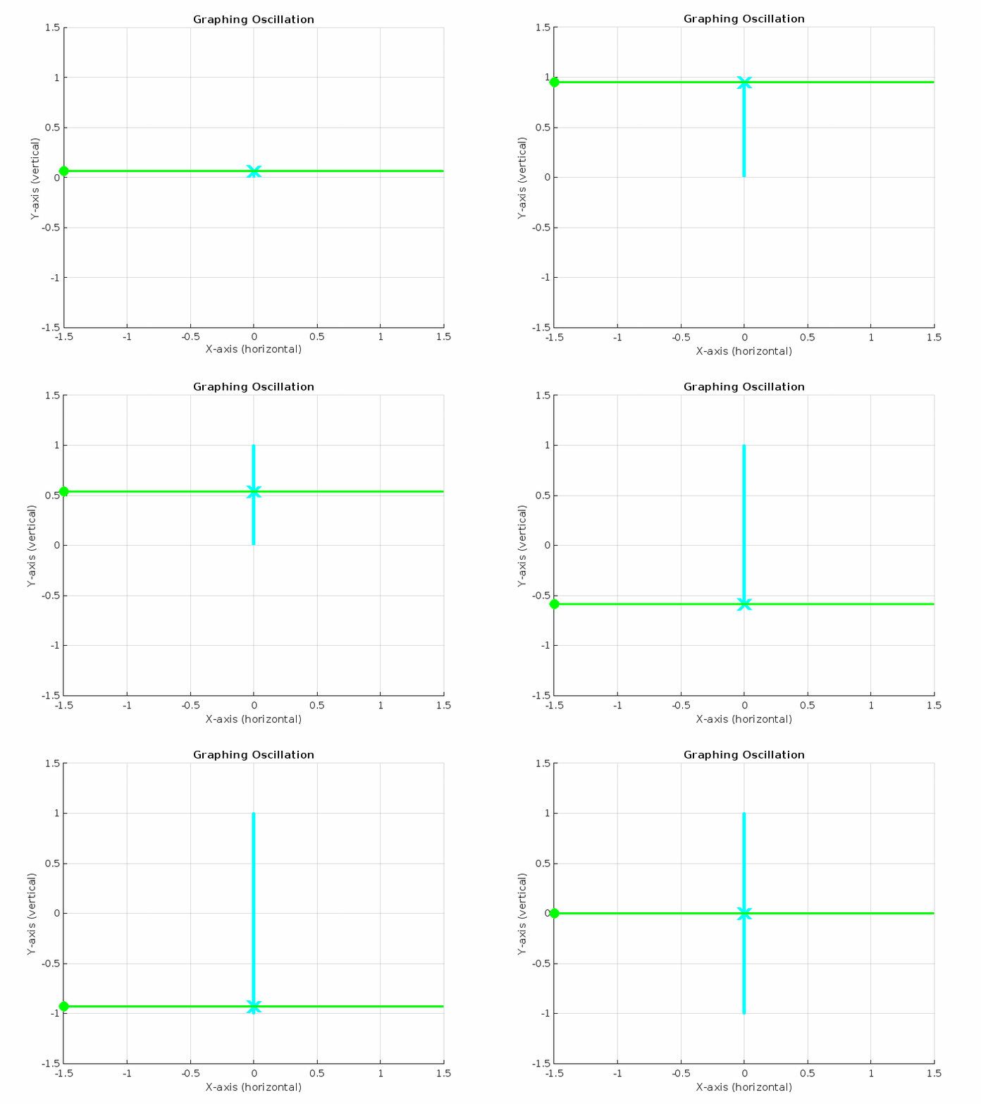


Using Two Axis
Using one axis we have seen how each of the oscillators can operate independently. For purposes of this discussion let me represent one of the oscillators for the single axis scenario like this:
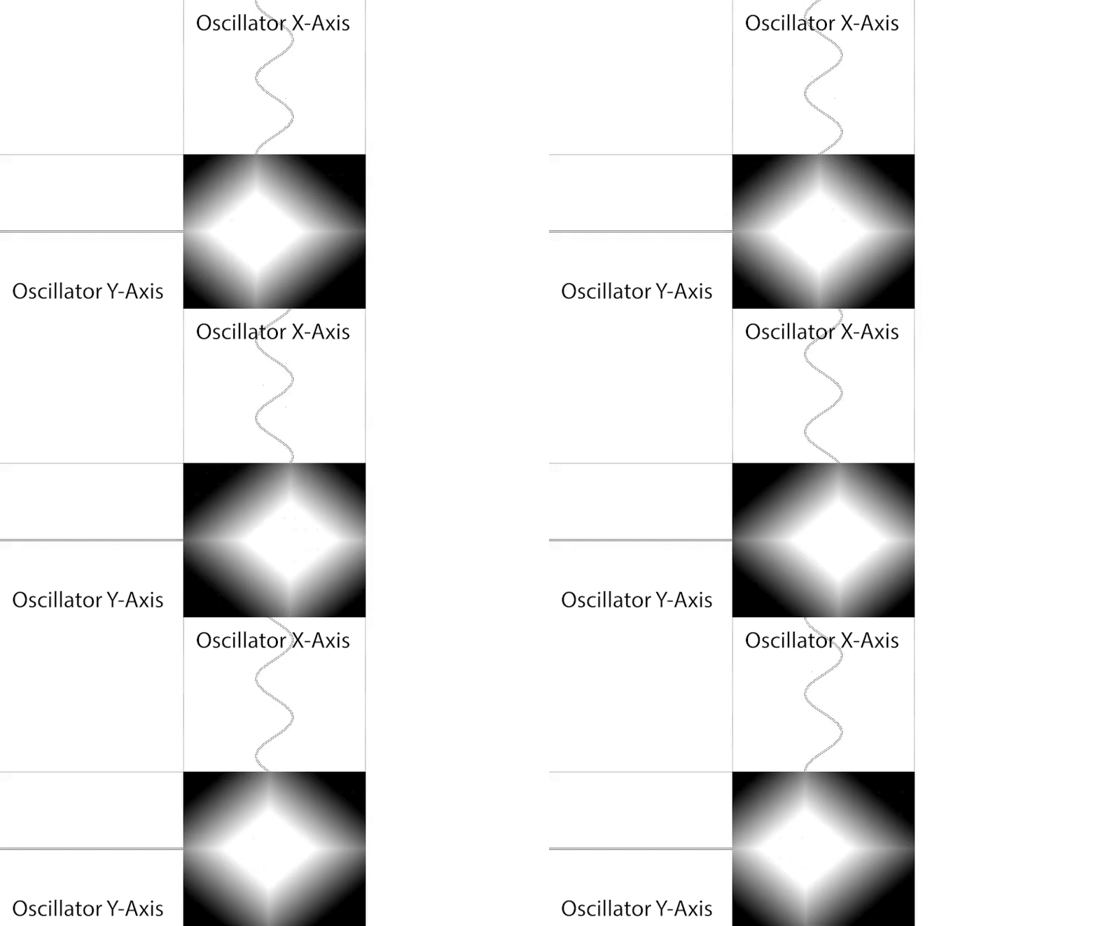
Here the oscillator is cycling in the x-axis direction and causes the viewer to be tugged in a left right direction. In the y-axis direction we have the oscillator turned off (Amplitude Y = 0).
Now let’s combine the oscillators together and mix them to do some clever things to enhance the experience. For this an explanation of phases is required. The phase is basically the starting point of the oscillation. The oscillator can be started during these phases in it’s cycle:
Each of these points is a quarter of a cycle behind from the previous. What is important here is that it doesn’t really matter when the cycle is started, what matters more is how the start of a cycle of one axis relates to the start of a cycle of the other axis. If they are the same then they are in synch and produce a diagonal oscillation as shown in the following illustration:
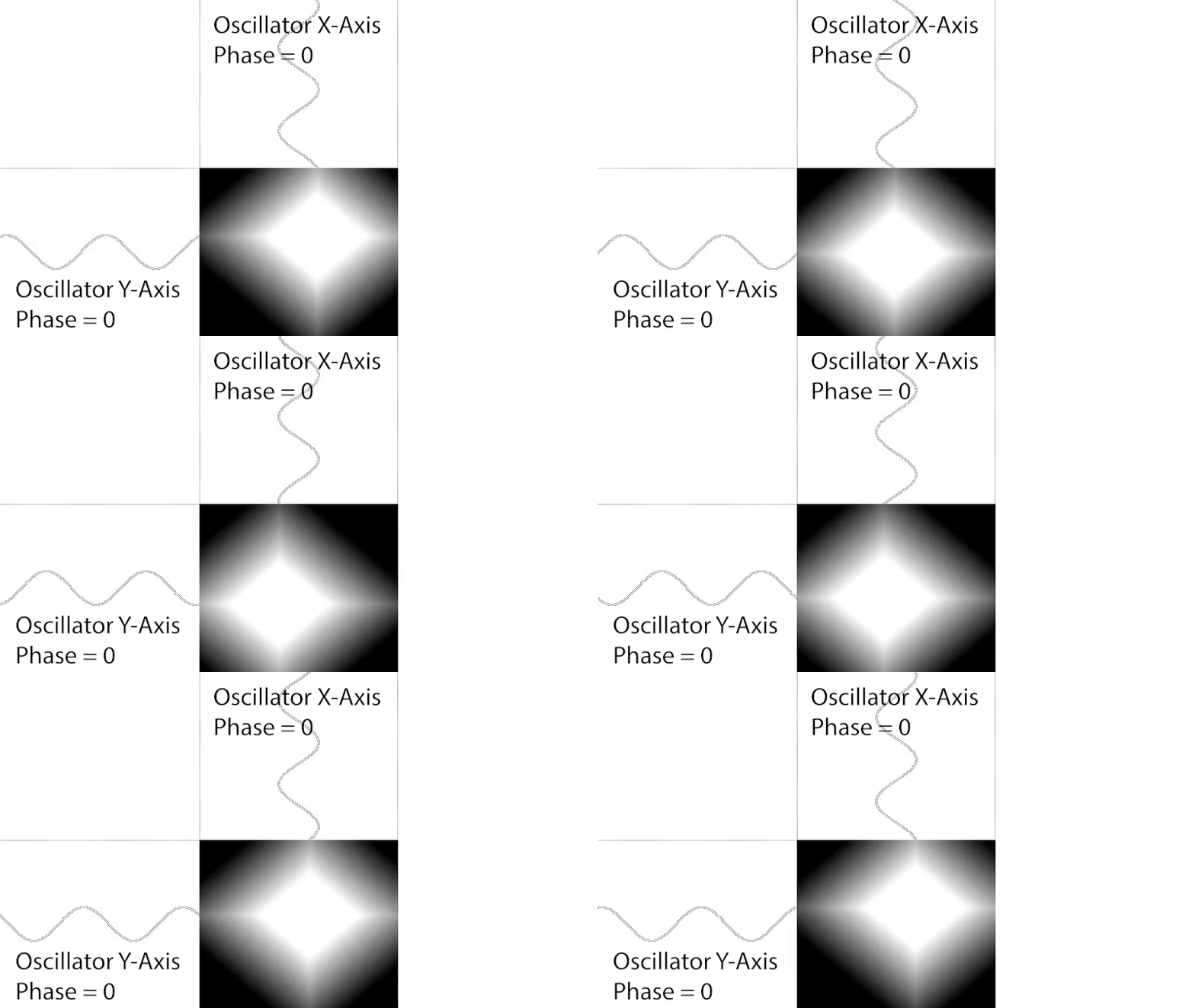
Note that the two oscillators follow each others motion. When oscillator for x-axis is at it’s peak, so is the oscillator for the y-axis. Similarly for when they are at their minimum or values in between. The two match their values perfectly and thereby trace out a diagonal line.
If however they are out of sync then they produce a loop in the form of a circle (or an ellipse if amplitudes differ) as shown in the following illustration:
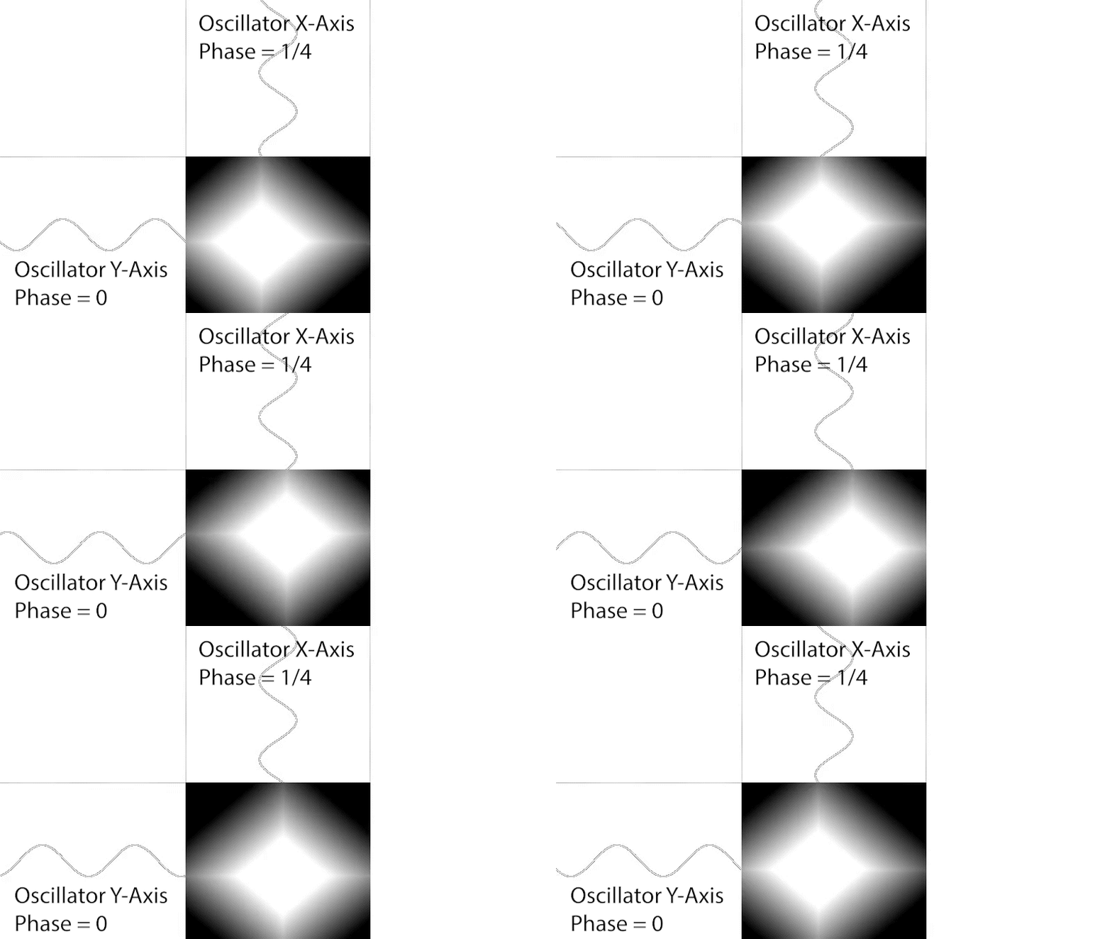
Note here that the two oscillators follow each others motion as well, but the oscillator for the x-axis is started by 1/4 of a cycle behind that of the y-axis oscillator. In other words the x-axis oscillator is “phase shifted” by one quarter of a cycle. This produces circular motion.
We covered the case here for no phase shift and 1/4 of a phase shift but you can also produce 1/2 and 3/4 phase shifts. These produce similar results:
- 1/2 phase shift produces diagonal oscillation similar to no phase shift, but moves from top left to bottom right.
- 3/4 phase shift produces circular motion, but in anti-clockwise direction.

Using Three Axis
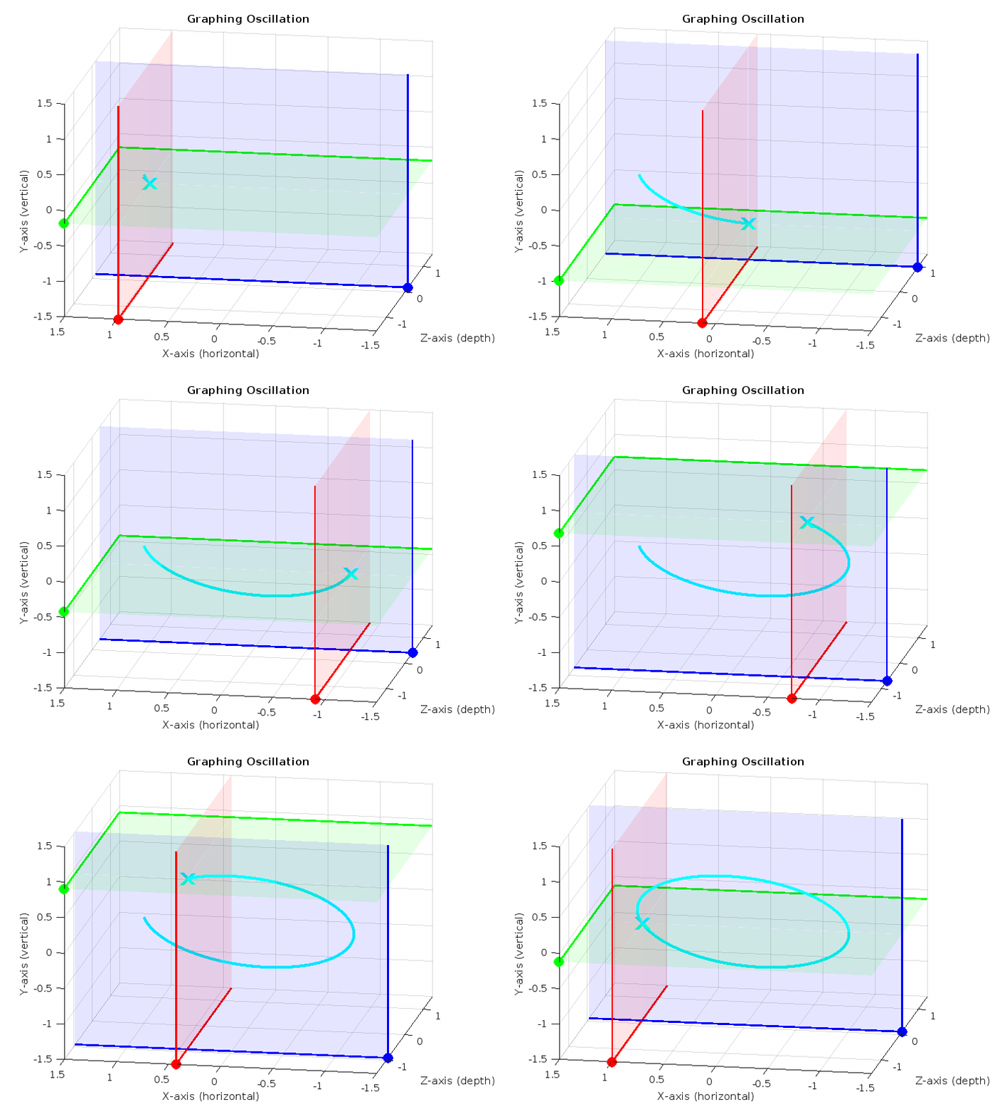
The concepts from the 1 and 2 axis scenarios can be extended to the 3 axis case. We can mix all 3 oscillators to produce linear or looped motion. With this, in addition to the flat loops, a circle loop can be stretched into the third dimension. One such scenario is illustrated below:
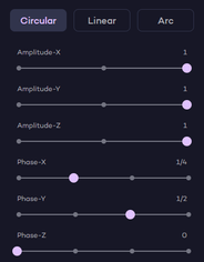
x-axis 1/4 phase shift
y-axis 1/2 phase shift
z-axis 0 phase shift

Manual Settings - Linear Mode
In this mode you specify two points and the viewer will be taken from the first to the second with a straight line motion. These are set using 3 sliders (one for each axis) for each of the 2 points.
A simple scenario is illustrated below:
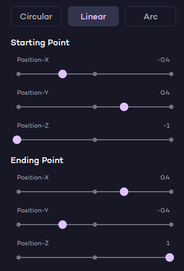

- From: (-0.4, 0.4, -1)
- To: (0.4, -0.4, 1)
Manual Settings - Arc Mode
In this mode you specify three points and the viewer will be taken through all three points in a sweeping arc motion. These are set using 3 sliders (one for each axis) for each of the 3 points.
A simple scenario is illustrated below:
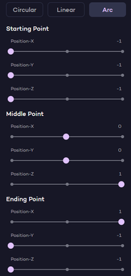

- From: (-1, -1, -1)
- Then To: (0 ,0 ,1)
- Finishing On: (1, -1, -1)
Depth Map Editing
The crucial piece of information derived from converting a 2D image to 3D within Immersity AI is the depth map. It contains information about the depth of every object in your image. It is a grayscale image that ranges from completely black to completely white. White represents objects that are close to the camera and generally comprise mostly of the foreground whilst black represents objects that are far away and generally comprise mostly of the background. Any gray shades in between represent objects that are between these two extremes and are positioned according to their grayscale value.
Whilst we are getting better and better at generating these depth maps, and we pride ourselves on the accuracy of the depth maps we produce, they are not perfect. They are generated from information that is not present and has not been measured. It is a best guess at the depth generated using AI techniques. As such there may be areas in the image where you know better from the context of the image or from actual more accurate knowledge of the scene. For this reason we provide the ability for you to make corrections to the depth map so that the resulting animation plays out more accurately.

In the example above, note how the horns of the goat are set too far back. to correct this, you can paint the depth of the head onto the horns and that then makes the horns move along with the head in the animation. To implement open the Depth Map Brush settings by selecting Depth Map from the menu:
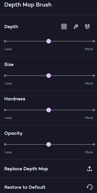
Then follow these steps to implement:
1. Identify objects that are incorrectly positioned with respect to depth
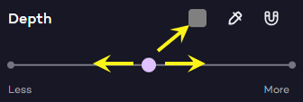
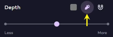
2. Set the paint brush to the depth that you want the object to be at. This can be achieved by either:
a. manually setting a depth using the Depth Slider
b. using the Eyedropper Tool to sample the depth at one location to then use it at another location
c. select the Clone Tool to simply extend the depth of an existing object.
3. Set the paint brush Size, Hardness and Opacity to get the right blending of brush with existing image on canvas
4. Paint the object with the Brush adjusting the paint brush settings along the way as needed to fill the entire object with required depth level.
5. Toggle the Overlay to blend in the image as needed. This can be used as a guide to help identify boundaries of the object you want to paint in. You can edit with overlay on or off.
6. Press Preview to see what your edits looks like along the way.
7. When all done, press Save and your new depth map is now in effect for the animation.
In the table below each of the features in the Depth Map edit environment is explained in more detail:
Example: If you have an apple and the apple stem is not at correct depth, you could start stroke on edge of apple itself where depth is correct and simply continue stroke onto the stem to make it same and part of the apple.

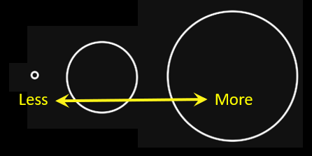

- More: If set to More then the brush acts strongly across entire brush circle.
- Less: As you move slider to the Less side, the edges of the brush circle start to act weaker. In other words, brush strokes on the edge of the brush take on more of the surrounding depth rather than the depth the brush is set to, whilst the center of the brush still acts strongly.


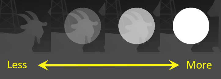
- More: If set to More, the brush will act strongly across entire brush circle.
- Less: As you move slider to the Less side, then the brush will take on some transparency across the entire brush circle. This leaves depth profiles partially in place underneath the stroke to the extent allowed by opacity slider. In other words the entire brush will not act as strongly on the underlying image leaving some depth profile in place.

- LiDaR device - using a scanner or some recent mobile phones including the iPhone that have these onboard.
- 3D Modeling application: Using a 3D model application such as Blender and rendering Depth rather than Image.
- Discard: this discards all of the edits performed in this editing session. Note that if you have previously saved edits, it will revert to these.
- Save: this will save the edits performed in this editing session.

